Imagewise luminance principle and application of the colorimeter
Optional electronic focusing lens series
With the increasing application range of color displays and the gradual improvement of its product quality evaluation system, accurate measurement of the chromaticity and brightness of displays has never been more important.
The imaging type luminance colorimeter can greatly improve the test efficiency, and has been gradually applied to the measurement of the display quality of television products in recent years. A comprehensive and in-depth understanding of the measurement principle of this type of equipment will help to better play its role and guide the test. Firstly, the measurement principle of the imaging luminance colorimeter is analyzed, compared with the realization principle of the point luminance meter, and then the design characteristics of the equipment are studied through design test experiments, which has guiding significance for practical test applications.
The traditional point-type luminance colorimeter uses a silicon photodiode (or photomultiplier tube) as a photoelectric receiving detector, which is characterized by small field of view angle, low cost, integrated spectrometer (more accurate measurement of tristimulus values), and compact size. It can measure parameters such as brightness illuminance, chromatic color temperature and color rendering coefficient, spectral radiation characteristic curve, etc. It is mainly used for measurement of LED spectral characteristics, calibration of conference room display, traffic light measurement, etc., more for point brightness colorimeter The details can be found in the detailed description of the corresponding model. For different test needs, different solutions need to be applied, such as measuring the display Mura value, testing the backlight keyboard, dashboard and panel brightness analysis of automotive and avionics, and the point-based luminance colorimeter has a small field of view, resulting in a small field of view. It is slow in the measurement of brightness uniformity of the display device and cannot meet the needs of the production line. At the same time, due to the user's demand for measurement visualization, an image color luminance meter using a charge coupled device (CCD or CMOS) as a detector has emerged. .
The point-type luminance colorimeter is a point-by-point imaging measurement. The imaging type luminance colorimeter uses an area array CCD or CMOS as a photoelectric receiving unit. Each CCD or CMOS pixel can be regarded as an independent detector, which can instantaneously measure the entire measurement. The surface is imaged on a CCD or CMOS sensor and the measurement speed is fast. The CCD or CMOS sensor can be regarded as a combination of X × Y dot luminance meters, and X and Y correspond to CCD or CMOS horizontal and vertical pixel numbers, respectively.
Although the image color brightness colorimeter is completely different from the standard device specified in the national standard, the measurement method is also very different, but it has been widely used.
This article on Westboro Photonics' latest WP640/690/6120 imaging colorimeter can be used for display display and calibration, brightness uniformity, Mura value, backlit keyboard, dashboard and panel test analysis for automotive and avionics , solid state light source analysis, beam distribution analysis. First, the test principle of brightness and chromaticity is introduced.
The Imaging Luminance Colorimeter is a metrology instrument that performs photometry and color measurement based on the imaging principle. The basic structure is a visual (or color vision) matching detector, optical system, and luminance chromaticity (using a three-color filter, The WP imaging luminance colorimeter uses a four-filter filter and other parameters of the signal output processing system.
Brightness test principle:
The measurement principle is shown in Figure 1.
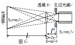
The relationship between the object surface and the image surface brightness is:
 (1)
(1)
Where: τ is the transmittance of the optical system; n' and n are the refractive indices of the image side and the object side, usually n'≈ n ≈ 1. Then the above formula is simplified to L'=τL. The brightness of the illuminant can be measured by measuring the brightness on the imaging surface.
According to Figure 1, the illuminance of the imaging surface can be derived using the principles of photometry and geometric optics:
Where E is the illuminance on the imaging surface; L is the brightness on the illuminating surface; Ï„ is the transmittance of the optical system; f is the focal length of the lens; l is the distance between the lens and the illuminating surface (referred to as the measuring distance); f m is The relative aperture of the system with f m =f/D, where D is the diameter of the aperture.
When the design of the system is such that f/l is small enough to be ignored (within a certain error range), the luminance L of the illuminant is linear with the illuminance E of the imaging surface.
Principle of colorimetric measurement:
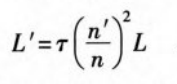
The chromaticity of the source is represented by the chromaticity coordinates x, y and is related to the relative spectral power distribution of the source. If the relative power distribution function of a light source is represented by P(λ), ` x(λ), `y(λ), and `z(λ) represent the CIE1931 standard spectral tristimulus values, as shown in Figure 2, then the source The tristimulus value can be expressed by the following formula:
The colorimetric measurement function of the filter type color luminance meter is realized by simulating the response of the human eye to light by using a suitable filter, so that the relative spectral responsivity of the detector after the addition of the filter is as shown in FIG. The CIE 1931 standard chromatic observer color matching function is shown to be close.
Note that in Figure 2, since `x (λ) also responds in the blue band, `x(λ) can be split into two filters, ie, the design of only three filters becomes four filters. Light film design for more accurate colorimetric testing.
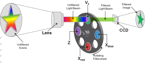
Figure 3 shows four filter designs for more accurate colorimetric testing.
WP640, WP690, WP6120 use Patel cooling CCD to minimize the noise and temperature drift of the test. A weak signal with a brightness lower than 0.01 cd/m2 can be reliably analyzed. Combined with the corresponding ND filter, the maximum measurable brightness can reach 1.5×10 7 cd/m 2 . An integrated point spectrum radiometer and a point strobe can be integrated.
WP comes with Photometrica@ software to provide users with a software environment, whether it is simple or in-depth analysis. Efficient automation with optional scripts or software development kits (SDKs), software test results and analysis capabilities, combined with a wide range of optional lenses to provide test-specific testing for industry applications solution.
WP6E/ES Series Imaging Luminance Meters: 640E/ES, 690E/ES, 6120E/ES, these instruments are unique in that their lens control allows for motorized zoom and iris control. These motorized zoom lenses provide high-resolution, high-precision imaging quality for their applications, and are easy to focus. Provides solutions for displays, illuminated keyboards, images and other luminance chrominance detection.
TUR Pack,TUR Drape Pack,Disposable TUR Pack,Disposable Sterile TUR Pack
Xinxiang Huaxi Sanitary Materials Co., Ltd. , https://www.huaximedical.com